










10 Tips for Choosing a Temperature Monitoring Sensor
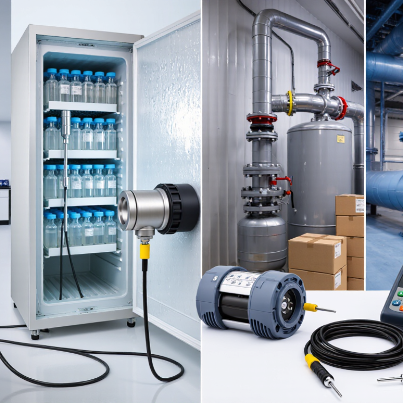
Choosing a temperature monitoring sensor is not just a matter of comparing prices or display features. The right device must fit the material, environment, measurement range, and response time your process requires. A sensor placed in a chilled storage room faces different conditions from one installed beside a hot pipe or inside a laboratory refrigerator. Small details matter. Probe length, cable durability, and sensor placement can all affect the reading.
A dependable choice begins with clear requirements. Consider the expected temperature range, the accuracy your work needs, and how often readings must be recorded. Check whether the sensor can connect to your existing monitoring system, and ask how it performs during power interruptions or communication failures. These practical questions help prevent gaps in the data. They also make routine checks easier. Manufacturer specifications are useful, but they should be reviewed against real operating conditions, not treated as guarantees. A sensor may perform well in a test environment and still be unsuitable for a damp, dusty, or frequently opened space.
The following ten tips explain what to assess before selecting a temperature monitoring sensor, from sensing technology and installation to calibration, alarms, and maintenance. There is no universal best option. Even a well-chosen device needs sensible placement and regular review. That part is sometimes overlooked. Use these points as a practical checklist, then confirm important requirements with the manufacturer or a qualified technician.
Define the Temperature Range and Monitoring Requirements
Before comparing sensor types, write down the lowest and highest temperatures the process may actually reach. Include routine operation, startup, shutdown, cleaning, and brief excursions. A freezer room might normally sit at -20°C, yet its door area can warm sharply during deliveries. Choose a measurement range that covers these conditions, with some margin, but avoid an unnecessarily broad range. Wider ranges can reduce useful resolution on some instruments. Check the sensor’s stated accuracy across the temperatures you expect to measure, not only at room temperature. Small details matter.
Tip: Match the sensor range to the real process, then verify accuracy and resolution at expected operating points. Decide how often readings are needed and how quickly temperatures can change. A storage cabinet may need periodic checks; a heated pipe may need faster sampling and an alarm. Define acceptable limits, response time, recording interval, and who should receive alerts. Start with the process.
Also note installation conditions. A probe touching a metal wall may report the wall’s temperature rather than the nearby product or air. Moisture, vibration, airflow, and cable length can affect performance. Specify where the sensing tip will sit and whether the installation can be checked or calibrated. In practice, “ambient temperature” is often too vague; name the exact point and expected conditions. Revisit assumptions after a trial, since real readings may expose a gap in the plan.
10 Tips for Choosing a Temperature Monitoring Sensor - Define the Temperature Range and Monitoring Requirements
| Tip | Monitoring requirement | Typical sensor choice | Typical measurement range | Selection note |
|---|---|---|---|---|
| 1. Define the full temperature range | Identify the lowest and highest expected temperatures, including start-up, shutdown, cleaning, and fault conditions. | RTD, thermistor, thermocouple, or infrared sensor, depending on the range and application. | Varies by sensor construction; common industrial RTDs cover roughly −200°C to 600°C, while thermocouples can cover wider ranges. | Check the specific probe, insulation, sheath, and instrument limits—not just the sensor type. |
| 2. Match accuracy to the process | Determine the allowable measurement error and whether readings are used for control, safety, or general trending. | Often an RTD for stable, accurate measurements in moderate temperature ranges; other technologies may suit different conditions. | Application-dependent. | Compare the complete measurement-chain accuracy, including sensor tolerance, transmitter, wiring, and calibration. |
| 3. Estimate the required response time | Decide how quickly the system must detect a temperature change to support control or alarm response. | A small exposed junction or thin probe may respond faster than a large, heavily sheathed probe. | Not a temperature range; response depends on sensor design and installation. | Ask for response time under the relevant medium and flow conditions; a published value may use a different test setup. |
| 4. Identify the measurement medium | Establish whether the sensor measures air, liquid, a solid surface, or a process stream. | Immersion probe for fluids; contact probe for surfaces; infrared sensor for non-contact surface readings. | Depends on the sensor and the material being measured. | For infrared measurement, account for emissivity, distance, target size, and intervening vapour or windows. |
| 5. Check exposure to moisture and chemicals | Consider washdown, condensation, corrosive media, cleaning agents, and process pressure. | A suitably sealed probe with compatible sheath, fittings, and cable entry. | Use the rated limits of the complete assembly. | Verify ingress protection and material compatibility for the actual installation; an enclosure rating does not establish chemical resistance. |
| 6. Choose the installation depth and location | Measure a representative point without creating an unacceptable obstruction or safety hazard. | Probe length and mounting style selected for the vessel, pipe, duct, or surface. | Application-dependent. | Poor placement can cause readings that differ from the process temperature, even when the sensor itself is accurate. |
| 7. Specify the output and control interface | Confirm how readings will reach a controller, recorder, building system, or monitoring platform. | Direct resistance or millivolt input, a transmitter output, or a digital interface. | Set by the sensor and connected instrument. | Check input type, wiring configuration, cable distance, electrical noise, and signal scaling. |
| 8. Determine logging and alarm needs | Define sampling interval, data retention, alarm thresholds, and whether alerts must operate locally or remotely. | Sensor paired with a suitable data logger, controller, or monitoring system. | Use a measurement range that includes normal operation and relevant alarm limits. | The logger’s input range, resolution, clock accuracy, and alarm behaviour also affect the monitoring result. |
| 9. Plan calibration and maintenance | Set calibration intervals and decide whether the probe must be removable or replaceable without major downtime. | A sensor assembly that can be checked or replaced using the site’s maintenance procedure. | Calibration should cover the operating temperatures that matter. | Calibration frequency depends on criticality, operating conditions, history, and applicable quality requirements. |
| 10. Allow for operating and safety constraints | Account for vibration, electrical hazards, hazardous locations, pressure, and applicable site or regulatory requirements. | A sensor assembly and installation method suitable for the specific environment. | Must remain within the rated limits of every component. | Confirm that required approvals apply to the complete installation; temperature suitability alone does not establish safety suitability. |
Note: Temperature ranges are indicative examples, not universal limits. Confirm the published ratings and accuracy specifications for the exact sensor assembly and measurement system.
Related Posts
-

Top Strategies for Enhancing Efficiency with Temperature Monitoring Sensors
-
Understanding Temp Sensors: How They Revolutionize Modern Climate Control Systems
-
What is the Best Temp Sensor for Your Needs?
-
What is a Temperature Sensor and How Does It Work?
-
How to Choose the Best Temperature Probe Sensor for Your Needs?
-
Unlocking the Power of Omega Heat Flux Sensors for Energy Efficiency in Modern Technology