










How to Choose a Contact Temperature Sensor?
Choosing the right contact temperature sensor begins with the application, not the product photograph. A sensor touching a polished metal pipe behaves differently from one pressed against a rough plastic housing. Surface material, temperature range, response time, pressure, vibration, and installation space all influence the reading. Even a high-quality probe can produce unreliable data when its tip sits loosely, faces an air gap, or uses unsuitable thermal paste.
Dr. Thomas J. Quinn, a respected temperature-metrology specialist, offers a useful reminder: “Temperature measurement is only as good as the measurement method.” That principle matters when selecting a contact temperature sensor. A thermocouple may suit fast-changing industrial equipment, while an RTD can provide stronger stability for controlled processes. Thermistors often deliver high sensitivity across narrower temperature ranges. The best choice depends on the required accuracy, wiring distance, controller compatibility, and maintenance conditions.
Small details matter. A clamp should hold the probe firmly without crushing it. A thin sensor may respond quickly but tolerate less mechanical stress. A thick probe may survive harsh use, yet react more slowly. These trade-offs are easy to overlook. I have seen specifications appear ideal until installation exposed poor contact or excessive cable noise. That is why selection should include a real mounting trial, not only a comparison table. No sensor is perfect. The reliable option is the one that matches the surface, environment, and measurement purpose with fewer compromises.
Understanding How Contact Temperature Sensors Work
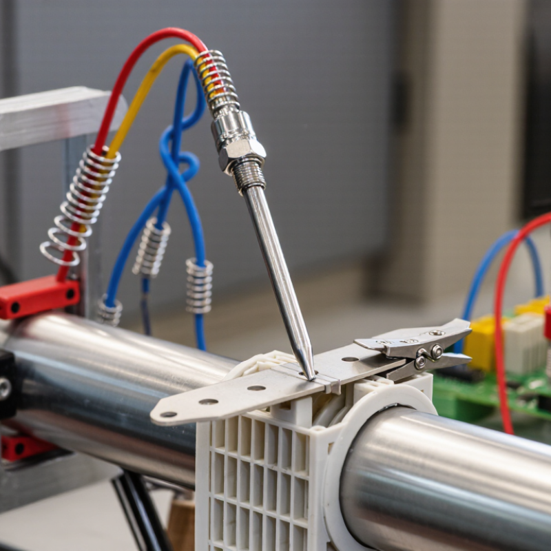
A contact temperature sensor measures heat through direct physical contact. Heat travels from the surface into the sensing element. The sensor then converts this thermal change into an electrical signal. An RTD changes resistance with temperature. A thermocouple produces a small voltage. A thermistor changes resistance sharply within a narrower range.
The sensor does not respond instantly. There is always a short delay. Choose the sensor by considering temperature range, response time, accuracy, and surface shape. RTDs suit stable processes requiring dependable accuracy. Thermocouples handle wider ranges and react quickly. Thermistors work well when high sensitivity matters within a limited range. Check the probe material and insulation before installation. A sensor that fits poorly may measure the air gap, not the surface.
Mounting pressure also affects the reading. A loose clamp can create thermal resistance between the probe and equipment. Use a suitable contact compound when the application allows it. Keep the sensing tip clean and fully seated. In field measurements, I have seen a correct sensor produce a wrong result because the cable touched a hotter pipe section. Small details matter. Calibration against a traceable reference improves confidence and reveals drift. Record the installation position, ambient conditions, and measurement uncertainty. It is tempting to trust a stable display, but stability alone does not prove accuracy. Recheck the setup when readings seem convenient rather than physically reasonable.
| Sensor Type | How It Works | Typical Temperature Range | Typical Accuracy | Response Speed | Best Contact Method | Main Advantages | Important Limitations | Recommended Applications |
|---|---|---|---|---|---|---|---|---|
| Thermocouple | Generates a small voltage when two dissimilar metals are joined and exposed to a temperature difference. | Approximately −200°C to 1,700°C, depending on the thermocouple type and construction. | Typically ±1.5°C or ±0.75% of reading for common industrial classes; actual performance depends on the type and installation. | Fast, especially with a thin wire or exposed junction. | Spring-loaded probe, welded surface junction, clamp, or high-temperature adhesive. | Wide temperature capability, rugged construction, low cost, and fast response. | Requires reference-junction compensation; signal levels are low and can be affected by electrical noise. Accuracy may drift with age and contamination. | Ovens, furnaces, exhaust systems, machinery surfaces, and rapid temperature changes. |
| Resistance Temperature Detector (RTD) | Measures the predictable change in electrical resistance of a metal element as temperature changes. | Approximately −200°C to 850°C, depending on the element, insulation, and sheath. | Common industrial platinum RTDs can achieve approximately ±0.1°C to ±0.5°C with suitable wiring and instrumentation. | Moderate; usually slower than a fine-wire thermocouple because of the protective element and sheath. | Flat surface probe, clamp-on probe, compression fitting, or spring-loaded mounting. | High accuracy, good repeatability, and relatively strong long-term stability. | More expensive than many thermocouples; can be damaged by vibration, shock, or excessive bending. Lead-wire resistance must be managed. | Process equipment, clean surfaces, laboratory systems, HVAC equipment, and applications requiring stable readings. |
| Thermistor | Uses the large, predictable resistance change of a semiconductor material with temperature. | Typically −50°C to 150°C; some specialized designs extend beyond this range. | Often approximately ±0.1°C to ±1°C over a limited operating range, depending on calibration and electronics. | Very fast when made with a small bead or thin-film element. | Adhesive-backed patch, epoxy attachment, clip, or small spring contact. | High sensitivity, compact size, low cost, and good performance over a narrow range. | Nonlinear output; operating range is usually narrower than that of RTDs and thermocouples. Long cable runs can introduce measurement errors. | Battery systems, electronics, medical equipment, small appliances, and low-to-moderate temperature surfaces. |
| Bimetallic Contact Thermostat | Uses two bonded metals with different thermal expansion rates to mechanically open or close an electrical circuit. | Commonly −50°C to 300°C, depending on the mechanical design. | Usually intended for switching control rather than precision measurement; differential and switching tolerances are specified instead of high measurement accuracy. | Moderate to slow, because the metal element must physically move. | Direct surface contact, threaded mounting, clamp, or embedded installation. | Simple, durable, self-contained, and does not require a separate signal-conditioning circuit. | Provides an on/off response rather than a continuous temperature signal. Switching hysteresis and mechanical wear may affect control. | Over-temperature protection, heaters, motors, compressors, and basic thermal cut-off systems. |
| Surface-Mount IC Temperature Sensor | Uses semiconductor circuitry to convert the temperature of the sensor package or attached surface into an analog or digital signal. | Commonly −40°C to 125°C; some industrial versions support wider ranges. | Often approximately ±0.5°C to ±2°C within the specified operating range. | Fast on thin surfaces with good thermal coupling; package size and mounting can limit response. | Thermal adhesive, soldered pad, mechanical clamp, or a thermally conductive interface material. | Direct digital output is available in some designs; easy integration with control electronics and good repeatability. | Requires electrical power and suitable circuitry. The measured value may be influenced by self-heating and nearby electronic components. | Electronic enclosures, circuit boards, battery packs, control panels, and low-temperature equipment surfaces. |
Related Posts
-
How to Choose the Right Temperature Probe Sensor for Your Needs?
-
How to Choose the Best Temperature Probe Sensor for Your Needs?
-
Top 10 Thermometer Sensor Types for Global Buyers
-
5 Essential Tips for Choosing the Right Temperature Sensor for Your Business Needs
-
Understanding How Temperature Probe Sensors Revolutionize Home Cooking and Food Safety
-
Best Temperature Probe Sensor for Accurate Measurements?